Build Your Own Approach Timer
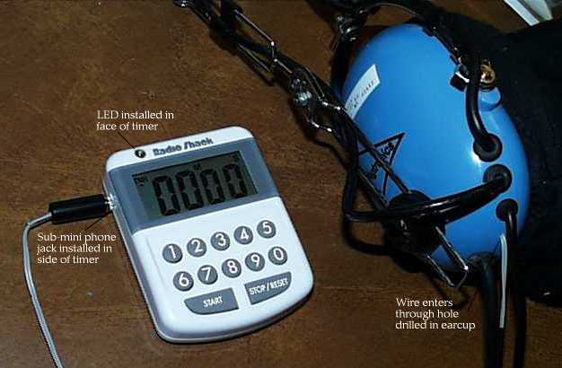
Radio Shack sells an inexpensive digital up-down timer that makes a pretty good approach timer if you velcro it onto a yoke clip. Here are a couple modifications I made to mine that make it (in my opinion) a better approach timer than you'll likely find for sale anywhere. The modifications:
- Add an LED to provide a visual cue that the timer's expired.
- Move the actual beeper into your headset.
Both modifications are easy assuming you can handle a soldering iron.
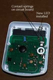
To perform either modification, you'll need to open the timer with a small Philips head jeweler's screwdriver (there are six screws on the back cover). The noise-maker ("beeper") piece is a small flat disc about the size of a quarter, attached to the back cover; all the other electronics are on a circuit board attached to the face of the timer. The connection between the beeper and the rest of the timer is accomplished by means of two small springs on the circuit board that make electrical contact with the beeper. These springs are conveniently easy to solder to.
Adding an LED
My first modification to the timer was adding an LED. I selected the biggest, brightest LED I happened to have on hand. I don't know the exact specifications, but you can easily test before installing by touching the leads of the LED to the timer while holding the battery in place: if the timer can light the LED when a countdown completes, your LED is suitable. You should also make sure you have the correct polarity by testing in this manner before installing.
I drilled a hole through the face of the timer just large enough to accomodate the LED. (It's tempting to drill the hole through the top edge of the timer, but be warned that many LEDs produce light only through the dome top, but are nearly invisible from the side.) Make the hole a close fit to the LED so that the LED is held in position by friction alone. Bend the leads of the LED so that they pass through the springs originating from the circuit board, and solder them to the springs.
The LED helps for keeping track of the time during night approaches, but it still doesn't solve the real problem of not being able to hear the timer in the noisy cockpit environment. The real solution for this is to relocate the timer's beeper into one of your headset's earcups. This involves modifying your headset (very slightly) in addition to the $13 timer, so it may take a little while to work up the nerve, but the risk is still minimal, and I think the results are worth it.
Remoting the Beeper
Start by opening the timer again (if it isn't already open), and remove the beeper from the back of the timer. As I mentioned, the beeper is about the size of quarter (only thinner), and there are actually two discs visible, separated by an insulator.
To bring the timer signal out of the timer itself, we'll drill another hole in the timer, and install a sub-mini (2.5") phone jack. I chose this jack for its small size, but perhaps something a little larger could be made to work. Before installing, solder a couple of short (maybe 2") leads to the jack, and make sure the leads can reach the same springs on the circuit board. Then drill through the timer case and tighten the jack in place. (To avoid interference with the timer's display, I drilled the hole through the seam where the face and back of the timer meet. Another arrangement I didn't try that might work is to install the jack in the back of the timer, but this will mean attaching wires between the front and back of the timer -- not the end of the world, but not as convenient to disassemble again should the need arise.) Once the jack is installed, bring the leads over to the springs and solder them in place. Reassemble the timer.
Now you'll need a length of flexible, small-gauge, two-conductor wire. I cannibalized an old AM radio earpiece, but that was a little extravagant. I say small-gauge wire because one end of this wire has to pass into one of the earcups in your headset, and a bigger hole to accomodate a bigger wire would probably need a rubber grommet to form a good seal. You'll need 6-8' of this wire.
On one end of the wire, attach a plug to match the jack you installed in the timer. (This was actually the trickiest bit of soldering for me. If you can find a jack already attached to a suitable wire, you're ahead of the game.)
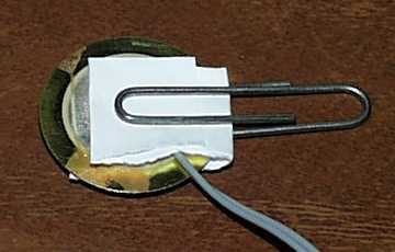
The other end of the wire will pass into the headset earcup through a hole you drill next. Disassemble the earcup before you begin, and make sure you're not about to drill through a circuit board or speaker. I used a 1/16" drill bit. After drilling through the earcup wall, I was able to "wobble" the bit to enlarge the hole into a small slot just large enough to accomodate the wire. Pass the wire from the outside of the earcup to the inside, and attach it to the beeper. I was concerned that the heat of soldering might damage the beeper, so I elected to use a simpler method: I bared the ends of the two conductors, and placed them on opposite faces of the beeper. Then I wrapped a small slip of paper around this sandwich (to act as an insulator), and held it all together with a small paperclip.
Plug the wire into the timer's new jack and verify that the relocated beeper still beeps. (If it doesn't, you might try reversing the wires; I'm not sure whether the beeper is sensitive to polarity or not.) Then reassemble the earcup with the beeper inside.
I found it helpful to tape the new beeper wire to the existing headset audio cable for about 3/4 of its length. This helps keep the wires from tangling in your flight bag, while still allowing for the timer wire and audio cable to separate near the panel.